
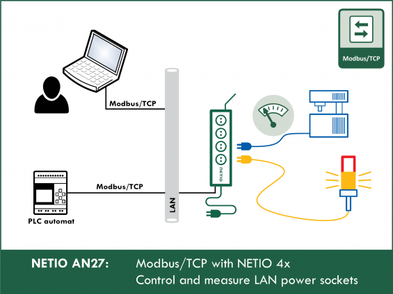
Modbus/TCP is one of the preferred protocols.
Advantages of Modbus/TCP:
- Very common standard, supported by most industrial devices and applications.
- IP Filter support in NETIO can provide a basic level of security.
- Many debugging tools are available for Modbus/TCP.
- The protocol allows writing values (control of outputs) as well as reading measurements from the device.
Actions applicable to each output (electrical socket)
In all M2M protocols, NETIO power sockets use the same actions that can be applied to individual outputs. For example, a Toggle or Short Off action can be written to any output. For Short On and Short Off actions, the Modbus/TCP protocol uses its own “short” time that is defined over Modbus.
However, it is only possible to read the socket states (0/1); the actions to be performed with the outputs are write-only.
- 0 = Output switched off (Off)
- 1 = Output switched on (On)
- 2 = Output switched off for a short time (short Off)
- 3 = Output switched on for a short time (short On)
- 4 = Output switched from one state to the other (toggle)
- 5 = Output state unchanged (no change)
Modbus/TCP functions
- 01 = Read Coils (NETIO: reads the On/Off state of one output)
- 02 = Read Discrete Input
- 03 = Read Holding Registers (NETIO: reads, for example, the number of outputs)
- 04 = Read Input Registers (NETIO: reads measurements)
- 05 = Write Single Coil (NETIO: sets the On/Off state of an output)
- 06 = Write Single Register (NETIO: performs the chosen action (such as toggling the state) with an output)
- 15 (0x0F) = Write Multiple Coils
- 16 (0x10) = Write Multiple Registers
|
|
Download Modbus / TCP specification |
| Supported devices: | NETIO 4All, NETIO PowerPDU 4C, NETIO 4, PowerCable Modbus, PowerBOX 3Px, PowerPDU 4PS, PowerDIN 4Pz, PowerBOX 4Kx, PowerPDU 8QS |
Setting up the device
In the NETIO 4x (NETIO 4 / 4All / 4C) web administration, go to M2M API Protocols - Modbus/TCP, check Enable Modbus/TCP, and if necessary set the port number. To allow the control of individual outputs, the Enable WRITE box must be checked. The IP address filter can be configured here, too (see below).

For NETIO PowerCable Modbus, the settings are similar.
Testing the Modbus/TCP API with the online demo
What is the online demo
The online demo is a real NETIO device connected to the internet with a public IP address. It can be used to test the web administration interface of the device and to control its outputs. The username / password combination is “demo” / “demo”.

In the online demo, configuration changes cannot be saved.
To access the online demo of any product, click “TRY ON-LINE DEMO” at the respective product page.
Note:
- The online demo of NETIO 4All and NETIO 4 allows read and write access using the Modbus/TCP protocol.
- The online demo of NETIO 4C only allows read access.
Online demos:
Device IP address
Most SW tools for working with the Modbus/TCP protocol require the IP address in the numerical form and cannot work with DNS names. To test the Modbus/TCP protocol with the online demo, it is necessary to find its current IP address (it changes from time to time).
A simple way to find the numerical IP address is to use the PING command. Enter the following command at the command prompt: ping netio-4all.netio-products.com. The Ping responses show the numerical IP address.

QmodMaster debug software for Modbus/TCP
To test the Modbus/TCP protocol, the QModMaster software can be used (available for download at https://sourceforge.net/projects/qmodmaster/).
QModMaster uses Wire addresses of individual coils and registers.
Wire Address = Register Address – 1
In other words, Wire Addresses start from 0, Register Addresses start from 1.
1) Set Modbus Mode to TCP

2) In the Options tab, select Modbus TCP…

3) Setting the IP address and port of the NETIO device
The software requires the IP address in the numerical form.

4) Click Connect to connect to the NETIO device

5) After a successful connection to the NETIO device, the color of the circle in the lower left-hand corner changes

Reading values from the NETIO device
- NETIO 4 / NETIO 4C devices allow reading the states of outputs O1 to O4.
- NETIO 4All / PowerCable Modbus devices support electrical measurements and can display the measured values over the M2M Modbus/TCP protocol.
Reading the frequency and voltage
- Function Code: Read Input Registers (0x04)
- Start Address: 0 Dec
- Number of Coils: 2
- Data Format: Dec
The request is sent by clicking the Read/Write button next to the Connect button.

The main pane should display 2 values.
- Frequency * 100 [Hz]
- Mains voltage * 10 [V]

Reading the states of the outputs (electrical sockets)
- Function Code: Read Holding Registers (0x03)
- Start Address: 101 Dec
- Number of Registers: 4
- Data Format: Dec
Click the Read/Write button to send the request.
The main pane displays the states of individual outputs (0 = OFF, 1 = ON).

Switching the O1 output ON (1-bit operation)
For writing to the outputs, NETIO 4x and PowerCable Modbus devices support bit-based operations (coils) as well as word-based operations (registers).
- Function Code: Write Single Coil (0x05)
- Start Address: 101 Dec
- Number of Coils: 1
- Data Format: Dec
- Main pane: 1 (ON)
Click the Read/Write button to send the request.

Toggling the O1 output state (register – Toggle output)
When writing, the value to be written needs to be entered. In this case, it is (the number of) the action to be performed with the output (the output number is specified by the address, O1 = 101, O4 = 104).
The actions are the same as in the other NETIO M2M protocols:
- 0 = Switch the output off
- 1 = Switch the output on
- 2 = “Short off” (switch the output off for a short time)
- 3 = “Short on” (switch the output on for a short time)
- 4 = Toggle (switch the output to the other state)
- 5 = Keep the current state
- Function Code: Write Single Register (0x06)
- Start Address: 101 Dec
- Number of Registers: 1
- Data Format: Dec
- Write field: 4
Click the Read/Write button to send the request.

If you have the device on your desk, you can immediately see that the output has switched. In the online demo, the change in the output state can be observed by opening the web interface in a browser.

NETIO Modbus/TCP
Overview of coil and register addresses
- The following is a brief description of coil and register addresses for NETIO Modbus/TCP.
- For the complete NETIO Modbus/TCP protocol specification, please ask the manufacturer.
| Register Address | Wire Address | R / W | Type | Function | Description | Read / Write Values |
| 102 | 101 | W | bit | 05 |
Switch on 1st output {coil) |
1 True |
| 104 | 103 | W | bit | 05 |
Switch on 3rd output {coil) |
0 False |
| 102 | 101 | W | uInt16 | 06 | Toggle 1st output state | 4 |
| 105 | 104 | W | uInt16 | 06 | Briefly switch off 4th output | 3 |
| 102 | 101 | R | bit | 03 | Read the 1st output state | 0 or 1 |
| 303 | 302 | R | uInt16 | 04 | Upper 2 bytes of the 1st output total consumption | 0 to 216-1 |
| 304 | 303 | R | uInt16 | 04 | Lower 2 bytes of the 1st output total consumption | 0 to 216-1 |
IP filter
- To increase security of the Modbus/TCP protocols, NETIO devices implement an IP address filter.
- The IP filter can be configured over the web interface.

- The first field (Start IP) specifies the start of the allowed IP address range.
- The second field (End IP) specifies the end of the allowed IP address range (up to and including this IP address).
- To configure the filter to accept a single IP address only (e.g. 192.168.101.115), enter that IP address in both fields.

- The IP address used to access the NETIO device is shown in the Last connection from field.
- When accessing the device from a different network, the originating IP address of the request and the IP address seen by the device may differ. It is therefore necessary to make sure from which IP address does the NETIO device receive requests.
EasyModbus Client
- To test the Modbus/TCP protocol, other utilities can be also used, such as the EasyModbus Client (http://easymodbustcp.net/).
- Unlike QModMaster, this tool uses Register addresses (all addresses are increased by 1).
- To connect, configure the mode, IP address and port, and click Connect.

Example of reading the states of all outputs using bit-based (coil) access.
EasyModbus Client uses Register addresses, not Wire addresses = the address to read Output 1 is 102 (in QmodMaster it was 101):

- Example of toggling all outputs:

FAQ:
1) Why Output 2 switches when trying to switch Output 1?
Due to the history of the Modbus protocol, some tools use “wire addresses” that are decremented by 1.
2) Is it possible to switch several outputs at once?
Yes. Use the Write Multiple Coils 0x0f function or the Write Multiple Registers 0x10 function and set the number of outputs in the Number of Registers section. The Start Address then specifies the number of the first register.
3) Is it possible to secure Modbus with a password?
No. However, it is possible to use the IP filter to restrict the IP addresses that can access the NETIO device using the Modbus protocol.
4) NETIO 4All provides registers to read the measured values. What do these registers contain for NETIO 4 and NETIO 4C?
The registers contain zeros.
5) When trying to write, QModMaster reports “Write data failed”.
Most likely, write access is disabled on the NETIO device, or the address is outside of the range allowed by the IP filter. Make sure that write access is enabled in the web interface (Enable WRITE (Enable output control)).
6) Is it possible to use Modbus/TCP utilities other than those described here?
Yes, we can also recommend e.g. Modbus Poll.
7) Are there any differences in the Modbus/TCP protocol between NETIO 4x products and PowerCable Modbus products?
No, except that the NETIO PowerCable Modbus only has one output, mapped as Output 1. The measured values are the same.
Supported FW versions:
3.1.0 and later (Firmware archive)