
For correct operation according to the following description, the NETIO device needs Internet access.
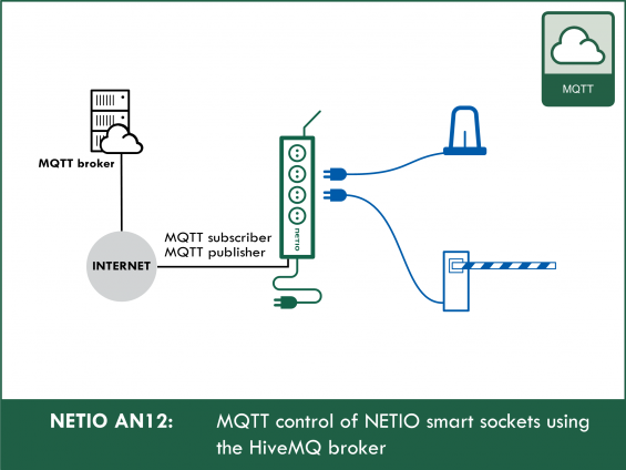
- NETIO power sockets behave as a MQTT subscriber.
- Based on the commands received, the device carries out the requested action (switch an output).
- NETIO device also works as a MQTT publisher to send messages with its measurements and output states (upon change, upon request, or periodically as configured).
The MQTT payload uses a JSON structure.
A message (MQTT payload – a string of characters) received by the NETIO device is decomposed into individual commands/actions which are then performed – the outputs are set as required or the complete device state is sent. The actions for each output are numbered the same way in all M2M protocols supported by NETIO:
- 0 = Output switched off (Off)
- 1 = Output switched on (On)
- 2 = Output switched off for a short time (Short OFF) – device restart
- 3 = Output switched on for a short time (Short ON)
- 4 = Output switched from one state to the other (Toggle)
- 5 = Output state unchanged (no change)
For actions 2 and 3, a Delay parameter (in milliseconds) can be specified in the message. If the parameter is omitted, the default value (defined in the web administration) is used.
What can NETIO 4All measure over MQTT
One particular product of the NETIO 4x series – the NETIO 4All model – measures electricity consumption individually for each of the 4 outlets. These values are published over MQTT. This particular model makes available:
- 1x electrical voltage [V]
- 1x grid frequency [Hz]
- 4x electrical current [A]
- 4x power [W]
- 4x consumption [Wh]
- TPF (True Power Factor) - for a sine waveform corresponds to Cos Phi
Supported devices: NETIO 4All, NETIO PowerPDU 4C, NETIO 4, PowerCable MQTT
Configuring NETIO 4x
In the NETIO 4x web administration, go to the M2M API Protocols - MQTT section, enable MQTT API, and set MQTT mode to “Generic”, “Broker Host” to “broker.hivemq.com” and “Broker Port” (the broker’s TCP port) to “1883”.
Then, the username and password for logging in to the broker need to be set. In the case of the public HiveMQ broker, authentication is not required and the username and password are ignored by the broker. However, these fields are mandatory in NETIO to enable and configure the MQTT API and need to be filled in.
Make sure that “Use SSL” is unchecked because the public HiveMQ broker does not support SSL connections. Next, fill in the “Client Id” – this will be used in the topic as the NETIO device identifier. At the same time, it is used as an identifier to the broker, and therefore it must be unique – we recommend to append the last 2 bytes of the device MAC address (without colons). When two (or more) devices use the same “Client Id”, they disrupt each other’s communication with the broker, and MQTT will not work correctly on any of them. Set the “Update period” and click Save Changes to save your settings.
Note: The “Update period” determines how often a MQTT message containing the states of all outputs (and measurements in case of NETIO 4All) is sent. When set to “0”, no periodic message is sent and only change messages for individual outputs are sent whenever an output state changes. (For NETIO 4All, messages about changes of the measured values are also sent; this can happen quite often due to voltage fluctuations.)

The NETIO 4x MAC address can be found in the NETIO 4x web administration under Settings / Network Configuration.

If MQTT is set correctly and the NETIO device has Internet access, the connection to the HiveMQ MQTT broker is established and the “MQTT status” changes to “Connected (Connected)”.

When the connection to the MQTT broker cannot be established, the “MQTT status” shown will be “Broker connection failed (Failed to connect: unknown reason)”. If this is the case, double check the broker address (“Broker Host”) and port (“Broker Port”), and make sure that “Use SSL” is unchecked. If all the settings are correct, verify that the NETIO device can access the internet.
Possible methods for checking the internet connection include synchronizing the time or checking for firmware updates – in the NETIO 4x web administration, go to Settings - Firmware and click “Check for updates”.

If, after a little while, an “up-to-date” indication appears, it means that the internet connection is working.

Should the connection to the MQTT broker still fail, we recommend to make sure that the HiveMQ broker is accessible from the network to which the NETIO device is connected. For example, in a browser on a computer, enter the broker.hivemq.com address; the browser should be redirected to http://www.mqtt-dashboard.com/ – if that is the case, the broker seems to be accessible and it is necessary to check if MQTT communication is not blocked by your network (router/firewall), e.g. by port filtering.
If, after clicking “Check for updates”, the “Operation has failed” error message is displayed, it means that internet is most likely not accessible from the NETIO device. Check your network settings and make sure that MQTT communication is not blocked, for instance by your router or firewall.

Setting MQTT “client”
To test the MQTT API functions, we recommend to use the MQTT Websocket client by HiveMQ to receive messages from the NETIO device and to control its outputs:
http://www.hivemq.com/demos/websocket-client/

The “Host” can remain set to “broker.mqttdashboard.com” or changed to “broker.hivemq.com”, both addresses point to the HiveMQ public broker. The port should remain set to “8000”, its Websocket Port. The “ClientID” is generated and unique; we recommend to keep it because it is not used anywhere else and it only identifies the client against the broker (you can set your own ClientID, as long as it is unique within the broker). The remaining fields should remain unchanged. Click “Connect”.
Connection to the broker is indicated with a green color; “Connected” appears and the Connection section is collapsed.

Now you can set the “Subscriptions” to receive messages from the NETIO device – click “Add New Topic Subscription”.

A dialog box to enter the “Topic” and related settings appears. For “Qos”, choose “0”. For “Topic”, enter “devices/<Client Id>/messages/events/”, where “<Client Id>” is the Client Id entered in your NETIO device – in our example it is “netio-test-25E0”, so the topic is devices/netio-test-25E0/messages/events/ . Click “Subscribe”.

The dialog box is closed and the newly added item appears in the Subscriptions section.

If the “Update period” specified in the NETIO device MQTT configuration is higher than “0”, then at most after the time specified, a MQTT message will be sent by the NETIO device and subsequently received by the client and displayed in the “Messages” section.

Similarly, a message will be displayed whenever the state of a NETIO device output changes.
MQTT message contents
- Information about the overall device state
- Voltage [V]*
- Grid frequency [Hz]*
- Total current through all outputs [mA]*
- Total power factor [-]*
- Total power [W]*
- Total consumption [Wh]*
- Measurement start time*
- Information about individual outputs
- Output ID
- Output name
- Current output state
- Action being performed with the output
- Time delay in case of actions 2 and 3
- Current through the output [mA]*
- Power factor [-]*
- Power through the output [W]*
- Consumption at the output [Wh]*
*These values are provided only by NETIO 4All

Switching an output over MQTT using HiveMQ
To control an output of the NETIO device, fill in the “Publish” section:
Topic: “devices/<Client Id>/messages/devicebound/”
where “<Client Id>” is the ID entered in the NETIO device – in our example it is “netio-test-25E0”, so the topic is devices/netio-test-25E0/messages/devicebound/
QoS: 0
Retain: unchecked
Message: {"Operation":"SetOutputs","Outputs": [{"ID":1, "Action":4},{"ID":3, "Action":4}]}
Click “Publish” to send the MQTT message to the broker and subsequently to the NETIO device, which then performs the requested action – in this case, toggles the outputs 1 and 3. In the “Messages” section, messages about the output state changes appear.

To request information about the complete device state (including the measured values for NETIO 4All), publish a {"Operation":"GetDescription"} message. The complete status message is again displayed in the “Messages” section.

FAQ:
1) Is it possible to disable the messages that notify about state changes (or changes in measured values in case of NETIO 4All)?
No. When an output state changes, communication with the MQTT broker takes place regardless of whether the output state was changed by pressing a local button, by an internal Lua script, over the Web or from the mobile app.
2) Is it possible to specify a minimum threshold by which a measured quantity needs to change for NETIO 4All to send a state change message? Currently the messages are sent even if, for example, the current changes by a few mA.
No, the current system uses internal events. We plan to change that and allow more detailed configuration of events.
3) What is the difference between MQTT Generic and MQTT (MS Azure)?
The difference is in the method of communicating with the MQTT broker. In MS Azure, everything is entered by the user as a specific string, and not in individual fields. This should make it easier to carry the configuration over to many devices.
4) Is it possible to change the structure of the MQTT topic and payload?
Not at this time. We plant to allow modifications from a Lua script in the device.
5) What are the recommended/required values of Retain and QoS?
Retain: To control NETIO 4x, we recommend NOT to use Retain messages. NETIO 4x does not mark outgoing messages with the Retain flag.
QoS: Depends on the MQTT broker used. When communicating with the broker, NETIO 4x uses QoS 1.
6) Is it possible to switch several outputs at the same time in a single MQTT message?
Yes, commands for individual outputs can be placed in a sequence. Example – to switch on all outputs: {"Operation":"SetOutputs","Outputs": [{"ID":1, "Action":1},{"ID":2, "Action":1},{"ID":3, "Action":1},{"ID":4, "Action":1}]}
7) Is it possible to include the time delay for the reset actions (Short ON / Short OFF) in the MQTT message for NETIO power sockets?
Yes, the message can include a “Delay” parameter to specify for how long (in milliseconds) should the output remain on/off. Example – to switch on output 2 for 5 seconds: {"Operation":"SetOutputs","Outputs": [{"ID":2, "Action":2, "Delay":5000}]}
8) Can the NETIO power sockets also communicate over MQTT with the Mosquitto MQTT broker?
Yes, MQTT on NETIO 4x will also work with the Mosquitto broker. We used HiveMQ in this Application Note because it is publicly accessible for testing without the need to install it.
9) Due to frequent changes in voltage, NETIO 4All sends messages quite frequently. How can I limit the number of MQTT messages?
It is not possible to limit the number of messages sent by the NETIO device. A message is sent upon every change of an output or a measured quantity.
10) Is it possible to connect NETIO 4x to AWS (Amazon Web Services) using MQTT?
No, not at this moment (07/2017). AWS currently requires a security certificate in the device, and NETIO 4x does not support that. In order to connect the device to AWS, it is necessary to use another MQTT server that is connected to AWS.
Supported FW versions:
3.0.1 and higher (Archiiv firmware)
Supported devices: