
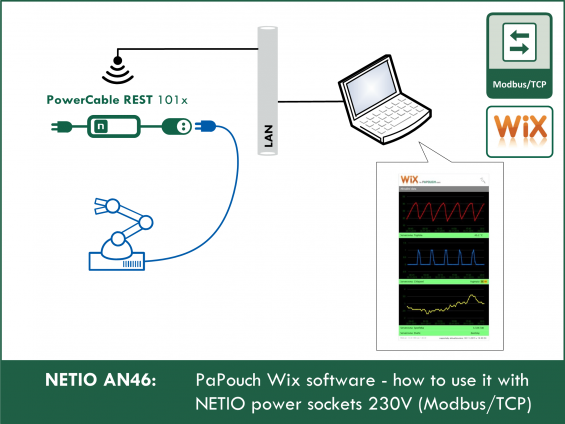
The AN46 Application Note demonstrates how to setup Wix Measurement software to communicate with NETIO smart power socket, control and show output state (On/Off) and display different graphs of measured electrical parameters.

Wix Measurement software capabilities which you can use with NETIO devices:
- Display current values from connected devices
- Display of the numeric value
- Display of a color bar (so-called bargraph) with color according to the current value
- Display text by current value
- Graph display
- Save measurement history to a text file for post-processing or evaluation
- Control NETIO device power output state (On/Off)
- Actions on set events
- Send an email
- Send SMS
Details about the M2M protocol: NETIO Support Download Modbus / TCP - description of NETIO M2M API interface - PDF
Supported devices:
Available soon in Wix:
- NETIO PowerPDU 4C
- NETIO PowerPDU 4PS (only show On/Off)
- NETIO PowerPDU 8QS
- NETIO PowerDIN 4PZ
- NETIO PowerBOX 3Px (only show On/Off)
- NETIO PowerBOX 4Kx
- NETIO 4 (only show On/Off)
- NETIO 4All
Configuring NETIO
In your NETIO device web administration go to M2M API Protocols - Modbus/TCP, check Enable Modbus/TCP and if necessary, set the port number.
The IP address filter can be configured here, too.

Installation of Wix Measurement Software
Wix is free to download at its official page. There is no need to install Wix. Just copy it to your computer and run it. (For saving the program creates a data subdirectory and creates new files in it.)
When you first start the program, Wix attempts to connect to the server www.papouch.com and get data about outdoor temperature in company headquarters. If it succeeds (if an Internet connection is available on the Wix PC), it will start display the measured temperature and its graph. This function serves as a demonstration of Wix measuring possibilities and you can test the program without having to have any compatible device.
How to add a new device to Wix Measurement
1) Press the “+” button or right-click the program window and select Add / Module.
2) The Device Type window will open, enter any caption first and then select the device type from the list – NETIO / Netio PowerCable.


3) In the following window ( Connection Settings ), type IP and port number of your NETIO device.

4) Another window ( Input setting ) allows you to name the quantity from the device, set it unit, display placeholder text instead of quantity or bargraph, and also recalculate measured value to another range

5) Click on OK and adding a new device to Wix is now complete.
How to add a new chart
You must have at least one device set up in Wix before adding a chart.
1) Press the symbol button “~+” or right-click the program window and select Add / Chart.
2) The Graph Settings window opens, where you first select one or more devices that they should be displayed in the graph and give them different colors.

3) Then enter the vertical range of the graph (Minimal and Maximum values) as well as the time span as horizontal range (Displayed Interval).
4) Click on the OK button and finish adding the chart.
Tip: The graph can be separated from other variables in a separate window. Just tap the graph right-click and select Move to another window (another Wix window is meant).
Storage settings
The storage configuration is accessible through any Wix panel. Right-click and in the menu select Settings and on it Saving tab. On it is a list of current tasks with archives which settings can be edited with the Edit button.

It is easiest to create a new archive via the wizard - store values. With its help you can select measured parameters to be saved to the file, separator of the records in the text file and so on. All changes are immediately reflected in the preview at the bottom of the window.

In the wizard, click the Create button to open the custom record storage configuration. At the top of the window you can set the job name, save interval and file location on the disk. At the bottom of the window, the format for saving data to a file is configured.

You can select from the tree to the right any values from the devices being measured, including units, names, etc.
Press OK when all parameters are set. This saves the job and saves the values to file. The list of all defined saves is on the Save tab
Setting events
Configuration of actions is accessible through any Wix panel. Right-click and in the menu select Settings and then Action tab. There is a list of current events. Items can be edited Individually with the Edit button.

If you want to add a new action, click Add. In the window that opens you can configure what action to perform. First, enter a Caption, that will identify the action among others. Then click on Add in the Condition list section.

Then select the event type. Options are available “range check”, “input error”, or “time condition”, Input and corresponding condition in “measured input value” field. Click on OK to add this condition.
The action is defined in Action list. You can do one of the following: Send email, Send SMS, and others (see the picture).

To send an e-mail, the PC with Wix must have access to the Internet.
To send SMS the TC35i GSM modem must be connected to PC.
Pressing the OK button saves the action and becomes active.
The list of all defined actions is on the Actions tab. Individual actions can be continuously arbitrary turn on and off using the checkboxes on each row. For example, you can pre-define various actions and then simply turn them on according to the current situation.
The free version of Wix is subject to the following limitations:
- the maximum of 10 panels or 5 devices.
- Impossible to hide the panel referring to Papouch.com.
- The chart, like the instant value, has two types of display: "actual values" and "historical data". Display settings of graphs can be changed at any time.
FAQ
1) How to control power output on the NETIO device from Vix?
Just simply click on icon “ON” or “OFF” next to the output state value.
2) Is it possible to secure Modbus/TCP connection between NETIO device and Wix?
Somehow. You can define allowed IP address range from what NETIO device accepts Modbus/TCP connection. Set it up at NETIO device web administration M2M API Protocols / Modbus/TCP /Enable IP filter. Use the same IP address if this is only one allowed.
3) Can I use NETIO Cloud in parallel to Vix connection?
Yes, NETIO Cloud works in parallel to Modbus/TCP protocol.
4) Can I use NETIO Mobile app in parallel to Vix connection?
Yes, NETIO Mobile app works in parallel to Modbus/TCP protocol.
Supported FW versions:
- PowerCable Modbus 101x: firmware 2.3.9 and later
- PowerPDU 4C: firmware 3.3.1 and later
- PowerPDU 4PS: firmware 2.4.4 and later
- PowerBOX 3Px: firmware 2.4.4 and later
- NETIO 4 and NETIO 4All: firmware 3.3.1 and later