
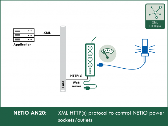
XML over http(s) is one of the preferred protocols.
Advantages of the XML protocol
- The XML file structure is easy to understand and there are numerous tools to work with XML.
- With https, the communication can be secured in a standard way.
- Transfer over http at the default port 80 makes XML- and http(s)-based M2M API protocols the least susceptible to problems with firewalls and security restrictions in large enterprises.
- The control is bidirectional.
- Using http get, the /netio.xml file with the overall status of the device and the states of individual outputs (sockets) can be downloaded.
- The outputs can be controlled by uploading the /netio.xml file using http post.
- User-friendly reading of the status (a simple click in the browser).
- To upload the XML files to the device, NETIO provides the HTTP(s) file upload function. It allows easy uploading of 3 .xml files prepared in advance.
How does the NETIO XML http(s) protocol work
- In the web administration, enable M2M API Protocols – XML API and leave the READ-ONLY access without a password. If the option was disabled before, save the changes (the device restarts).
- The status of the NETIO 4x device (sockets ON/OFF + electricity consumption for NETIO 4All) can be found in /netio.xml at the device’s IP address. The netio.xml file is downloaded over http(s) and displayed in the browser just as a usual web page.
- Device control using XML is somewhat more complex: it is necessary to upload a “netio.xml” file in the correct format to the NETIO 4x device using the correct password over http(s) at the correct port. The http(s) protocol may also ask for a password for uploading the file.
- Files can be uploaded using a variety of tools and utilities. To make things simple, NETIO users can use our HTTP(s) file upload tool. Ready-made .xml files can be used to verify the functions of the XML protocol. See the next sections for details.
-
In the NETIO implementation of the XML protocol, it is possible to upload the netio.xml file (using http post) and download the updated netio.xml file after the action is performed in the course of a single TCP/IP connection to the http server.
The XML file description (a XSD file) can be downloaded from the device. For a detailed description of the NETIO XML protocol structure, see the M2M XML documentation. Please use the form to request the latest version.
Actions applicable to each output (electrical socket)
In all M2M protocols, NETIO power sockets use the same actions that can be applied to individual outputs. For example, a Toggle or Short Off action can be written to any output. However, it is only possible to read the socket state (0/1); the actions are write-only.
- 0 = Output switched off (Off)
- 1 = Output switched on (On)
- 2 = Output switched off for a short time (short Off)
- 3 = Output switched on for a short time (short On)
- 4 = Output switched from one state to the other (toggle)
- 5 = Output state unchanged (no change)
Supported devices: NETIO 4All, NETIO PowerPDU 4C, NETIO 4, PowerCable REST, PowerBOX 3Px, PowerPDU 4PS, PowerDIN 4Pz, PowerBOX 4Kx, PowerPDU 8QS
XML M2M API example using the online demo

What is the online demo
The online demo is a real NETIO device connected to the internet with a public IP address. It can be used to test the web administration interface of the device and control its outputs. The username / password combination is “demo” / “demo”.
In the online demo, configuration changes cannot be saved.
To access the online demo of any product, click “TRY ON-LINE DEMO” at the respective product page.
Online demo for NETIO 4ALL: http://www.netio-products.com/en
XML API settings in the NETIO 4All demo:

The netio.xml file can be displayed by clicking the link in the web interface:
http://netio-4all.netio-products.com:8080/netio.xml.

Contents of the netio.xml file from the online demo:

You can test the control of NETIO smart sockets over HTTP XML with a product on your desk as well as with the ONLINE DEMO device. For a description of how to upload a .xml file with a set of commands in the HTTP(s) file upload tool, see below. The same method can be used with the online demo, too.
XML file to toggle output 1
Example of a simple .xml file that toggles the state of the first output:

Contents of the file to toggle the first output:
How to test the XML interface of NETIO 4x
The following description assumes that you have the NETIO 4x smart sockets device on your desk. The online demo can be also used for the testing.
Enable XML API
In the NETIO 4x web administration, go to M2M API Protocols - XML API and check the Enable XML API checkbox. The device can be used in 2 modes. In the READ-ONLY mode, it is only possible to read data from the NETIO device (GET). The READ-WRITE mode is used to control the output states.
Each mode uses a different password. The password can be empty.
Click Save Changes to save the settings. After saving the changes, the device restarts (about 1 minute).

Switching the outputs using a ready-made xml file
- The web interface of the NETIO devices includes the HTTP(s) file upload tool to upload an .xml file to the device.
-
At the XML API configuration tab, there are three ready-made example .xml files that you can download.
- Set output 1 to ON - turns on output 1
- Set output 1 to OFF - turns off output 1
- Toggle output 1 - changes the state of output 1
1) Downloading the ready-made .xml file
The example .xml file can be downloaded and saved to disk by clicking one of the links.

2) Saving the example .xml file to disk

After saving, the .xml file can be opened and edited e.g. in Notepad or WordPad.

3) Using the HTTP(s) file upload tool
Click Upload XML file to the device to open the HTTP(s) file upload tool. It allows uploading xml files from the local PC to the device.
Opening the HTTP(s) file upload tool:

Click “Upload XML file to the device” to open the HTTP(s) file upload tool:

4. Configuring HTTP(s) file upload
-
Host
- http://<NETIO_IP>/netio.xml
- Leave the default settings (current device)
- Notice that regardless of the name of your .xml file, it is always uploaded as /netio.xml
-
Port
- The default port is 80
-
Username
- User name for READ-WRITE access
-
Password
- Password for READ-WRITE access
- Click the Choose file button and select the .xml file previously downloaded to the PC (and, if necessary, modified).

5) Uploading the file using HTTP(s) file upload
- Click Send file to upload the file.
- When more files are selected, they can be uploaded in the proper order.

After the .xml file is uploaded, the outputs are set to the desired states. If you cannot physically see the device, you can check the output states at the Outputs page in the device administration.
After the .xml file is uploaded, the “Response” box shows the response from the NETIO device. The response is a complete .xml file that, for instance, confirms that the output was toggled.
If the response is not displayed (“---” or “error” appears), check the settings.
Description of the netio.xml file structure
This section briefly describes the XML structure of the netio.xml file.
A detailed description can be found in the XML M2M documentation that is available upon request.
- The netio.xml file can be downloaded from the device (if the XML API is enabled) as /netio.xml or by clicking the link in the bottom-left part of the “Test XML API” section.

- For the XML structure, a XSD description file is available. It can be downloaded by clicking the “Download XML Schema (XSD)” button.
")
XML file structure
The structure consists of three main sections.
-
Agent
- This section contains the main information about the device (model, firmware version etc.).
-
GlobalMeasure*
- Here are the measured variables that concern the device as a whole (voltage, frequency, total current and so on).
-
Outputs
- This section contains the states of individual outputs. Each output has its own Output section, distinguished by ID.
-
ID
- Output ID.
-
Name
- Name of the output, it can be changed in the web administration in the Outputs section.
-
State
- Current state of the output (0 or 1).
-
Action
- Action to perform with the socket; when reading, the value is always 6.
-
Delay
- Delay for actions 2 and 3. Configurable in the web application in the Outputs section (Switch delay).
-
Current*
- Current through the given output in milliamps.
-
PowerFactor*
- Power factor for the given output.
-
Load*
- Output power supplied through the output in watts.
-
Energy*
- Consumption at the given output in watt-hours.
(* Variables containing the measurement results are available only for devices with the energy metering capability.)
For a complete description, XML documentation is available upon request.
Creating a control XML file
The XML file to be uploaded to the NETIO device must contain the necessary tags only.
Every XML structure must be enclosed in:
Or, a simplified version:
- To work with the outputs, it is necessary to follow the prescribed XML file syntax.
- Then, an Output section needs to be created for each output that should be changed.
-
With each output, one of the following actions can be performed:
- 0 = Output switched off (Off)
- 1 = Output switched on (On)
- 2 = Output switched off for a short time (short Off)
- 3 = Output switched on for a short time (short On)
- 4 = Output switched from one state to the other (toggle)
- 5 = Output state unchanged (no change)
- For each output, the ID and Action variables need to be specified.
- To set the output state, the State variable can be also used (the only allowed values are 0/1 – Off/On). However, in this case, the Action variable needs to be set to 6 (it is mandatory so it cannot be omitted). The output is then set according to the State variable.
- Example – to turn on output 1:
Example – to turn on output 1 using the State variable:
Example – to toggle all outputs at the same time:
- In case of actions 2 and 3, it is possible to directly specify the time delay for the action using the Delay variable. The delay is specified in milliseconds (minimum 100ms).
- Example – to apply action 2 (Short Off) to output 1 for 3 seconds:
Three example files
An example XML file for controlling output 1 can be downloaded directly from the web interface of the device:
XML API - Download example XML API file.
- Set output 1 to ON
- Set output 1 to OFF
- Toggle output 1

Return values
The HTTP server status response to the xml get/post request can be any of the following:
-
200 OK
Everything went OK
-
400 Bad request
Syntax error in the request.
-
401 Unauthorized
Incorrect username or password.
-
403 Forbidden
XML API is disabled in the NETIO device (see Configuring NETIO 4x) or is read-only (and a write access was attempted).
-
500 Internal Server Error
Internal server error, or the server has not started yet (e.g. after a restart).
When the action is successfully executed, a XML file with the device status is returned. Its format corresponds to netio.xml.
In case of an error, a XML file is also returned, such as the following:
Bad request
Changing the port number
The XML over HTTP(s) protocol can use the same port as the web administration (80 by default), or a different M2M HTTP port.
The port can be changed in the web administration using the Use custom M2M HTTP(S) port option. When checked, the port can be specified in the Custom M2M HTTP(S) port field. The port change needs to be confirmed by clicking the Save Changes button.

FAQ:
1) Is it possible to control several outputs at once with a single command?
Yes, the XML API can control multiple outputs.
Example – to toggle outputs 1 and 2:
2) I am trying to upload the netio.xml file using the “HTTP(s) file upload” tool at the device website but the sockets don’t react. What could be wrong?
Double-check the steps described above. The most frequent causes of problems are:
- The M2M protocol is not enabled (M2M API Protocols - XML API - Enable XML API).
- The .xml file is uploaded to an incorrect address (the only correct address is http://<NETIO_IP>/netio.xml, where <NETIO_IP> is the IP address of the NETIO device).
- The .xml file is incorrectly structured (the correct xml format is described above).
- Wrong username or password (the username and password must match those in the READ-WRITE part in the XML API web configuration).
- The NETIO device is disconnected (network failure).
3) I turn on the socket using XML but then the Scheduler is supposed to control the same socket. Will the time sequence work as expected?
Yes, after executing a XML M2M API command, the socket can still be controlled via all other channels (Scheduler, WatchDog, mobile app, button, ...).
4) Is it possible to use a different port than 80?
Yes, in the web administration, the port can be changed using the Use custom M2M HTTP(s) port option.
5) What is the difference between the Action and State variables?
The State variable is primarily used for reading. Its value is 0 or 1 depending on the state of the output. The Action variable is used to set the output to the desired state.
6) How often is it possible to upload netio.xml to the NETIO device?
Due to the http server limitations, the frequency is limited to about 1-2 requests per second. This value can change when using https.
7) Is it possible to use other software tools to upload the xml?
Any software that can upload a XML file can be used, such as Advanced REST client or cURL.
8) What is the difference between xml and json M2M protocols?
The difference is only in the text file format, the method of uploading is the same.
9) Is it necessary to include end-of-line characters (CR+LF) at the end of each line in the xml file?
NETIO accepts most end-of-line character combinations. The xml file can be sent as a single line, too.
10) Is it necessary to upload the XML file as a netio.xml file?
Yes, the XML upload target must be /netio.xml.
Any other URLs will be ignored.
Supported FW versions:
3.1.0 and later (Firmware archive)
Supported devices:
- NETIO 4
- NETIO 4All
- PowerPDU 4C
- PowerPDU 4PS
- PowerBOX 3Px
- PowerDIN 4Pz
- PowerCable REST 101x