
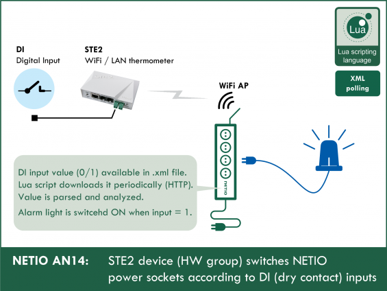
The script runs in the NETIO smart sockets device and every second reads the xml file with the status of the STE2 device. According to digital input states (0/1), electrical sockets of the NETIO device are switched on/off. In case of network or power failure, the output is set to a pre-defined state (0/1). When the connection is re-established, the script continues to run.
Digital inputs (DI) of the STE2 can be activated with any mechanical switch (dry contact) or a relay contact.
STE2 Web Thermometer

- Recommended third-party device
- Manufacturer: HW group s.r.o. (Czech Republic)
- Product: STE2: WiFi and Ethernet Thermometer with Digital Inputs
- WiFi temperature and humidity sensor with two digital inputs for dry contacts. Connects to the network via WiFi or Ethernet with PoE (802.3af) support. STE2 is supplied with a power adapter and a temperature probe. STE2 wifi and ethernet thermometer supports SNMP. STE2 online thermometer can be connected to the SensDesk online portal or to a SMS gateway.
Supported devices:
NETIO 4All, NETIO PowerPDU 4C, NETIO 4
Communication between NETIO 4x and STE2
1) NETIO 4x sends a CGI request to STE2
2) STE2 sends a xml response
3) NETIO 4x parses the required value from the xml response, compares it with the variable and switches the output if needed
Example of the STE2 xml response:

The highlight shows the ID and state of input 1
Connecting NETIO 4x and STE2
LAN connection
1) Connect STE2 with an Ethernet cable to your Local Area Network.
2) Connect NETIO 4x with an Ethernet cable to your Local Area Network.
NETIO as Wi-Fi Access Point
1) Connect STE2 with an Ethernet cable to your Local Area Network.
2) Connect NETIO 4x with an Ethernet cable to your Local Area Network.
3) Switch NETIO 4x to the Wi-Fi Access Point mode.
4) Connect STE2 to the network created by NETIO 4x.
Determining sensor ID
- The dry contact ID can be found physically on the STE2 (see the picture) or in the web interface.

- After connecting STE2 to your network, find its IP address using the HWg-Config utility.

- Sensor ID is shown in the STE2 web interface in the DIGITAL INPUTS section, in the ID column (see the picture).
- If a wrong sensor ID is specified, the error is written into the NETIO log and the action is terminated.

Creating the rule
To create and run the Lua script, do the following:
1) In the Actions section of NETIO 4 web administration, click Create Rule to add a rule.

2) Fill in the following parameters:
- Enabled: checked
- Name: STE2 - DI inputs (user-defined)
- Description: Switching according to DI inputs (user-defined)
- Trigger: System started up
- Schedule: Always
3) Copy the following code and paste it into the field for the Lua script:
------------Section 1------------
local output = 2 -- select output number (1 - 4)
local validValue = 1 -- select state for closed DI input
local invalidState = 0 -- select state for invalid values
local interval = 1 -- choose the period between controls (seconds)
local sensorID = 2 -- sensor ID
local ipSTE2 = "192.168.101.165" -- IP of your device
---------End of Section 1---------

local value = 0 -- internal variable, do not change

function call() -- send request on STE2
  cgiGet{url="https://" .. ipSTE2 .. "/values.xml", callback=getTemperature}
end

function control() -- check value
  --devices.system.SetOut{output=4, value=false}
  if value == 0 then
    devices.system.SetOut{output=output, value=1-validValue}
  else
    devices.system.SetOut{output=output, value=validValue}
  end
  delay(interval,function() call() end)
end


function getTemperature(o)
   if o.result == 0 then
     local myxml = o.buffer
     if xml.check(myxml) then
       local parsed = xml.parse(myxml,xml.STRIP_PREFIXES)
       local nmbOfSensors = # (parsed.get("BinaryInSet").children())
       local sensor = parsed.get("BinaryInSet","Entry")
       for i=1,nmbOfSensors do
         idVal = tonumber(sensor.get("ID").text)
         if sensorID == idVal then
           sensor = sensor.get("Value").text
           value = tonumber(sensor)
           control()
           return
         else
           sensor = sensor.next
         end
       end
       logf("Can´t find sensor with ID: %d, shutting down protocol", sensorID)
     else
       log("Invalid XML, next attempt in 10s.")
  	   devices.system.SetOut{output=output, value=invalidState}
  	   --devices.system.SetOut{output=4, value=true}
  	   delay(10, function() call() end)
     end
   else
     log(string.format("CGI get failed with error %d: %s. Next attempt in 10s.", o.result, o.errorInfo))
     devices.system.SetOut{output=output, value=invalidState}
     --devices.system.SetOut{output=4, value=true}
     delay(10, function() call() end)
   end
end

call()
4) To finish creating the rule, click Create Rule at the bottom of the screen.

Method of operation
- The temperature and humidity values measured by the STE2 and its digital input states are available in its web interface. There they can be checked.
- NETIO sends an http request and STE2 sends back a values.xml file with sensor values and digital input states.
- The Lua script looks for the configured input ID and processes its value.
- The Lua script parses the state of the digital input and sets the output accordingly.
- The cycle periodically repeats.
Setting the variables
- output
- Specifies the socket to control.
- Example – to control socket 1: output = 1
- validValue
- Specifies the output state to set when the digital input is closed.
- To switch off the output when the input is closed, set validValue = 0; to switch it on, set ValidValue = 1
- invalidState
- Specifies the socket state to set if there is an error (e.g. STE2 power failure, network failure etc.).
- To switch off the output in such cases, set invalidState = 0; to switch it on, set invalidState = 1.
- sensorID
- Specifies the ID of the input to monitor (see above).
- Possible values are 1 and 2.
- Example – to monitor the input with ID 1: sensorID = 1
- ipSTE2
- Specifies the IP address of the STE2 device. The IP address can be found with HWg-Config (see above).
- It is a string, so it has to be in double quotes.
- If the STE2 device uses a HTTP Port different from the default 80, the port needs to be specified after a colon.
- Example (port 80): ipSTE2 = "192.168.101.165"
- Example (port 8080): ipSTE2 = "192.168.101.165:8080"
STE2 – Third party product

STE2 web thermometer with LAN or WiFi connectivity is produced by HW group s.r.o. (Czech Republic).
- For more information, see www.HW-group.com / STE2.
- NETIO products company does not sell these devices; this example only shows our customers a potential use of NETIO products
The green digital inputs are used to connect a button or a switch. These inputs can be connected to “dry contacts” (voltage-free contacts) such as mechanical buttons or switches; HW group calls such devices “detectors”. NETIO 4x can react to a digital input being closed/opened, as shown in this Application Note.
The manufacturer includes a temperature probe in the STE2 package. A humidity sensor can be also connected to the sensor port. NETIO can work with data from these sensors as well, as shown in NETIO AN13.
For reacting to STE2 failures, see NETIO AN09 – the network presence of the device can be checked by sending PING requests to its IP address and a NETIO socket can be switched on if there is no response.
FAQ
1) Is it possible to connect the devices even without an Internet connection?
Yes, STE2 can connect to a WiFi network created by a NETIO4 or NETIO 4All in the Wi-Fi Access Point mode (NETIO Configuration mode). See Connecting NETIO 4x and STE2
2) Is it possible to control several outputs of a NETIO device with this method?
Yes. All output control takes place in the control function. There, any output behavior with respect to the contents of the value variable can be programmed.
3) Is it possible to check the digital inputs more often than once per second?
No, one second is the minimum.
4) Is it possible to monitor the readings from sensors connected to a STE2?
Yes. For details, see NETIO AN13.
5) Can I read from both digital inputs at the same time?
Yes. However, to keep things simple, we recommend creating another script with a different sensor ID. Values can be passed between scripts within a single device using global variables. It is also possible to read several variables in a single script but it requires more changes to the code.
6) Can I use this rule to work with digital inputs of a Poseidon2 device by the same manufacturer (HW group s.r.o.)?
Yes, the code will also work for Poseidon2 devices, the xml files are very similar. Tested with Poseidon2 3266, firmware version 1.4.8.
7) What happens if I restart one or both devices?
When the STE2 is restarted, the output is set according to the invalidState variable. When the device is switched on again, the monitoring of digital inputs will continue. When the NETIO 4x smart sockets device is restarted, the script is started again after power up. When the NETIO device is off, the script does not run and the inputs are not monitored. When both devices are turned off (e.g. due to power outage) and then back on, the sockets will again start reacting to the digital inputs.
8) Is it possible to detect faults (STE2 failure, torn off probe, ...) and signal them by switching another outlet on or off?
There are 3 commented-out commands in the code. These commands turn on socket no. 4 if the STE2 device is inaccessible. They are:
--devices.system.SetOut{output=4, value=true} and --devices.system.SetOut{output=4, value=false}. Simply uncomment these commands. One of them is in the control function and two more are in the getTemperature function. By changing the number in the output parameter, the socket no. 4 can be changed to any other socket.
Supported firmwar versions:
3.0.0 and higher (Archiv firmwware)
This Application Note is compatible with:

|
NETIO 4NETIO 4 is smart power socket (smart power strip) with four 230V/8A sockets, connected to LAN and WiFi. Each of the four power sockets can be individually switched on/off using various M2M API protocols. NETIO 4 is a unique product designed for IT, industry, smart homes, multimedia installations and other applications. Use the product whenever you need 230V sockets controlled by a mobile app, by a computer program (via M2M API) or by a custom script (Lua), and featuring a timer (Scheduler) or auto reboot functionality (IP WatchDog).
|

|
NETIO 4AllNETIO 4All is a PDU module featuring four 230V/8A power sockets with consumption metering for each socket as well as LAN and WiFi connectivity. Each of the four sockets can be individually switched on/off over the Web or using various M2M API protocols. Electricity consumption (A, W, kWh) can be measured at each power socket. NETIO 4All smart sockets are designed for remote measurement and control of electrical sockets. Use the product whenever you need 230V sockets controlled by a mobile app, by a computer program (via M2M API) or by a custom script (Lua) that runs directly in the NETIO 4All smart socket device. |

|
NETIO PowerPDU 4CNETIO PowerPDU 4C is a small 110/230V PDU (Power Distribution Unit). Each of the four IEC-320 C13 outlets can be independently controlled (On / Off / Reset / Toggle). Electrical parameters (A, W, kWh, TPF, V, Hz) are measured with high accuracy at each outlet. The device features two LAN ports (and a built-in Ethernet switch) for connecting to a LAN. Each power output supports ZCS (Zero Current Switching) to protect the connected equipment. |