
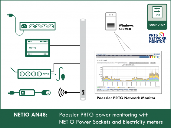
PRTG Network Monitor is a L7 network monitoring software, compatible with Windows. PRTG can gather statistical data from specified hosts, such as switches, routers or servers. It can monitor Windows, Linux, Unix and MacOS machines. PRTG supports SNMP, WMI, NetFlow, packet sniffing as well as monitoring of IPv4 and IPv6 devices.
PRTG only supports read-only access over SNMP; to control the outputs, an external utility is needed, such as the one described in AN51.
Supported devices:
- SNMP v1: PowerPDU 4PS, PowerDIN 4PZ, PowerBOX 3Px
- SNMP v1/v3: PowerPDU 4C, NETIO 4, NETIO 4All, PowerBOX 4Kx, PowerPDU 8QS
The AN48 covers following:
- Configuring the NETIO power socket device – SNMP v1 (Simple Network Management Protocol)
-
Configuring PRTG with the help of:
- OID (object identifier in SNMP)
- MIB file (a table of OIDs)
- .odt file (PRTG library with predefined OIDs)
- Displaying measured values and outlet states
- Setting up e-mail notifications based on a measured value
The advantage of using PRTG for monitoring NETIO power sockets is that it allows to monitor many sockets in a single concise environment and automatically send e-mail notifications whenever a value exceeds a defined limit.

Link: https://www.paessler.com/prtg
PRTG can monitor NETIO power sockets thanks to SNMP support.
For NETIO smart sockets, PRTG can:
- Display socket state (On/Off)
- Display a graph with a history of electrical measurements at a socket (Wh, W, A, Hz, power factor). NETIO smart socket device with measurement support is required.
- Indicate and notify that the measured power (W), current (mA) or consumption (Wh) has dropped below a specified minimum or risen above a specified maximum. NETIO smart socket device with measurement support is required
- Display availability history of the socket device (ping) and notify in case of any outages.
NETIO device configuration - SNMP protocol
SNMP support must be enabled at the NETIO device.
Using the web administration interface, the NETIO device can be configured as follows:
Enabling SNMP protocol
- LEFT MENU: - M2M API Protocols
-
Check „Enable SNMP” and verify the settings:
- port (default: 161)
- SNMP version (default: „1,2c“)
- community (default: „public“)
- Save changes
This example uses the unsecure 2c version for reading. This version is also enabled in the online demo at http://netio-4all.netio-products.com/


NETIO 4All online demo
The Online demo is a physical NETIO device connected to the Internet at a public IP address. The manufacturer makes available a demo device of each model. The online demos have different configurations, so it is possible to test the behavior without having the devices physically in hand.
In the online demos, configuration changes cannot be saved.
To access the online demo of a product, click “TRY ON-LINE DEMO” at the respective product page.
Configuring PRTG with OIDs
In SNMP, an OID is the address of a variable. Adding individual OIDs in PRTG is the fastest way to configure the connection.
Add a new device in PRTG: Devices / Add device

The address can be specified as a domain name (no protocol, no slashes) or a numerical IP address.

Configure the SNMP credentials.

The new device can be found in Devices / Device List

Device details

After clicking the selected device, add a sensor by clicking the „![]() " icon in the sensor list.
" icon in the sensor list.

For the sensor type, select SNMP Custom.

The OID needs to be entered in the sensor settings.
OID is the address of a value in the SNMP protocol.
OID is the identifier of a variable. It is the “long” number that defines the position of the variable in the tree of variables.
Some programs for working with SNMP do not support MIB files. In this case, OID strings need to be entered manually.
These strings can be found in the MIB table. However, to save you some time in first experiments with SNMP, a list of several variables with their OIDs follows:
1.3.6.1.4.1.47952.1.1.1.2.x Name of the output X
1.3.6.1.4.1.47952.1.1.1.3.x State of output X
1.3.6.1.4.1.47952.1.1.1.25.x Load at output X
1.3.6.1.4.1.47952.1.1.1.26.x Energy consumed at output X
1.3.6.1.4.1.47952.1.1.1.27.x Start time for energy consumption measurements at output X
1.3.6.1.4.1.47952.1.1.1.28.x Current drawn at output X
1.3.6.1.4.1.47952.1.1.1.29.x Power factor at output X
1.3.6.1.4.1.47952.1.2.1 Input voltage
1.3.6.1.4.1.47952.1.2.2 Frequency
1.3.6.1.4.1.47952.1.2.3 Input current
1.3.6.1.4.1.47952.1.2.6 Total consumption
Where to find SNMP OIDs
- NETIO documentation of the SNMP protocol
- AN11: SNMP management of 110/230V power outlets from the command line in Windows and Linux
Configuring the SNMP query of an external device in PRTG:

Configuration PRTG with a MIB file for the entire device
The MIB file can be used to simplify the adding of all sensors in a NETIO power socket device.
The .mib file is a text file that describes individual variables supported by the device. It contains the addresses, names, descriptions and numeric formats of the variables.
PRTG does not support inserting MIB files directly. It is necessary to use the MIB Importer to create an OIDLib library for PRTG from the MIB file. The library is then available in PRTG when the “SNMP Library” sensor type is used. In this way, it is easy to import sensors that output text; however, Paessler MIB Importer does not support, for example, dates.
In the web interface of the NETIO smart socket, go to M2M API Protocols > SNMP and click “Download MIB file” to download the MIB file
Open the MIB Importer by Paessler AG
MIB importer is available for download here: https://www.paessler.com/tools/mibimporter

Import the MIB file into Paessler MIB Importer:
File > Import MIB file
If needed, some parameters of individual sensors can be modified in the Importer. However, there are certain limitations; for example, it is not possible to set the DateAndTime format. As a result, such values will be displayed incorrectly. This can be avoided with an .odt library. However, for the sake of this demonstration, let us import the MIB using the Paessler MIB Importer.
The final result needs to be saved as an OIDLib library for use in PRTG:
File > save complete OIDLib (Netio library.oidlib)
File > save for PRTG Network Monitor
In the PRTG web interface (e.g. localhost), add a new device:
Devices > Add Device > select the group and click OK
The Add Device to Group Group window:
- Device name: Demo NETIO 4 All
- IPv4 Address/DNS Name: netio-4all.netio-products.com
-
Credentials for SNMP Devices:
- SNMP Version: v2c
- Community String: public
- SNMP Port: 161
- OK
Now, when the NETIO socket is connected, connect the sensors using the OIDLib. The procedure is the same as if adding a separate SNMP sensor, except that the “SNMP Library” sensor type is chosen and then the created library is selected:
Devices > All > Demo NETIO 4 All > Add Sensor > SNMP Library
- Select the saved library (Netio library.oidlib)
-
Selecting sensors from the MIB library
- The display of time since the start of the consumption measurement (netioOutputEnergyStart) is not supported
Configuring PRTG with an .odt file
MIB Importer does not support some data formats, such as dates. The simplest solution is to use an .odt library. (It is not the OpenDocumentText format but rather a text file with data in a defined structure)
Download the file: NETIO-4x-Mib-for-PRTG_PDU.odt
The library cannot be imported directly from the PRTG web interface. It has to be placed in the program’s file structure:
Place the Netio_PDU.odt file to the following folder: C:\Program Files (x86)\PRTG Network Monitor\devicetemplates\
In this case, we are not adding sensors to an existing device. Rather, a completely new device is created and then scanned according to the pattern in the .odt library.
In the PRTG web interface (e.g. localhost):
Devices > Add Device > select the group and click OK
The Add Device to Group Group window:
- Device name: Demo NETIO 4 All
- IPv4 Address/DNS Name: netio-4all.netio-products.com
-
Auto-Discovery Level: Auto-discovery with specific device templates
- New_Netio_Pdu
-
Credentials for SNMP Devices:
- SNMP Version: v2c
- Community String: public
- SNMP Port: 161
- OK
It takes a few minutes to discover all sensors. In Devices > All, “Auto-Discovery in progress (0%)” is temporarily shown for the new device.
Displaying measured values and output states
The newly added sensor can be manually updated.

If “Socket error” appears, most likely the DNS name or IP address is incorrect. It has to be specified without “http://” and without a trailing slash.

Correctly configured sensors:

More detailed graphs can be generated for a specific sensor at the Historic Data tab


Setting up notifications based on a measured value
Configuring Error or Warning notifications if a limit is exceeded
- Devices > All > Demo NETIO 4 All
- click the sensor name > Overview > Channel > Value > Edit channel settings
Sending an e-mail when the limit value is exceeded for longer than a certain time
- Devices > All > Demo NETIO 4 All
- click sensor name > Notification Triggers > Add Treshold Trigger

Sending an e-mail when the notification lasts longer than a certain time.
- Devices > All > Demo NETIO 4 All
- click the sensor name > Notification Triggers > Add State trigger

The resulting notification e-mail looks like this:
