
Supported devices: NETIO 4All, NETIO PowerPDU 4C, NETIO 4, PowerCable REST, PowerBOX 3Px, PowerPDU 4PS, PowerDIN 4Pz, PowerBOX 4Kx, PowerPDU 8QS
Node-RED is a unique tool, allowing to graphically connect program nodes. In its examples, NETIO uses standard nodes such as http get, XML parsing and so on to explain the processing of data.
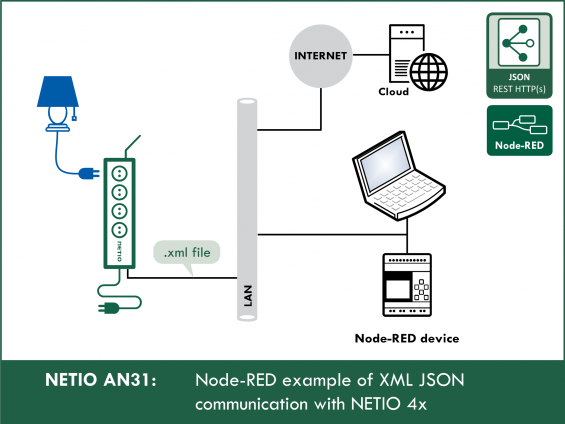
The NETIO AN31 Application Note shows two examples of working with NETIO smart outlets using http transfer of netio.xml files.
- The first example demonstrates the measurement functions and options, as well as the control of one outlet (Output 1).
- The second example, AN31v2, is a simplified version that can serve as a template for your Node-RED projects.
The first AN31 Node-RED flow demonstrates the control of output no. 1 from the Dashboard that runs in the Node-RED environment. Five buttons displayed in the Dashboard call the five possible actions that can be performed with the output (off, on, short off (restart), short on, toggle). The netio.xml file is sent to the http server of the smart socket device using http POST.
The dashboard periodically displays the states of all outputs as well as the measured values from the NETIO 4x device (current, voltage, total load), as long as the device is capable of measuring them. The reading of the output states and measured parameters takes place by downloading the netio.xml file every second from the http server of the NETIO smart socket device using http GET.
Details about the M2M protocol: NETIO XML http(s) REST protocol specification
Node-RED
The Node-RED environment can run on a PC, a Raspberry Pi, in a cloud (MS Azure, IBM) and so on.
Node-RED is very popular, so we have prepared more examples:
Flow (Node-RED script) for AN31:

Dashboard for AN31:
")
How does the NETIO REST XML http(s) protocol work
The current outlet state when reading (0 / 1) is in the State variable. This variable is read/write, as long as the Action variable is omitted or set to 6.
If the Action variable in the uploaded netio.xml file is set to a value different than 6, it takes priority and the value in the State variable is ignored.
Actions applicable to each output (electrical socket)
In all M2M protocols, NETIO power sockets use the same actions that can be applied to individual outputs. For example, a Toggle or Short Off action can be written to any output.
However, the Action variable can only be used for writing values, it cannot be used to read the current outlet state.
- 0 = Output switched off (Off)
- 1 = Output switched on (On)
- 2 = Output switched off for a short time (short Off)
- 3 = Output switched on for a short time (short On)
- 4 = Output switched from one state to the other (toggle)
- 5 = Output state unchanged (no change)
- 6 = Ignored
The value of 6 in the action tag means that the action is ignored and the outlet state is set according to the “State” variable (allowed values are 0 and 1 only). See the M2M XML documentation.
Example XML file to toggle output no. 1
<set:Root xmlns:set="http://www.netio-products.com/XMLSchema/NETIO.xsd">
<Outputs>
<Output>
<ID>1</ID>
<Action>4</Action>
</Output>
</Outputs>
</set:Root>
Configuring NETIO 4x
In the M2M API Protocols - XML API section of the NETIO 4x web interface, enable XML API.
Set the Username and Password for READ-WRITE access.
READ-WRITE credentials allow both reading and writing. The same READ-WRITE credentials can be used in both HTTP Request nodes (POST and GET).
Click Save Changes. After saving the changes, the device restarts (about 1 minute).


NETIO 4All Online demo
The online demo is a physical NETIO device connected to the Internet at a public IP address. The manufacturer makes available a demo device of each model. The online demos have different configurations, so it is possible to test the behavior without having the devices physically in hand.
In the online demos, configuration changes cannot be saved.
To access the online demo of a product, click “TRY ON-LINE DEMO” at the respective product page.
Node-RED
Node-RED is a programming tool for wiring together hardware devices, APIs and online services in new and interesting ways. Node-RED provides a browser-based flow editor and a wide choice of nodes and options. It is built on Node.JS, making it ideal to run on low-cost hardware such as the Raspberry Pi as well as in the cloud.
AN31 flow
The Node-RED configuration is specified in a json structure and can be pasted via the clipboard.
")
Importing the AN31 flow to node-RED
In the menu, select Import -> Clipboard.
Then, copy the text to the indicated field and click Import.
 script as clipboard in Node-RED")
Installing missing nodes
The nodes are loaded into the selected flow. It is possible that an error message is displayed with a list of nodes that are being imported but are not installed in Node-RED yet. In this case, the missing nodes need to be installed.
If there are nodes missing, select Manage palette in the menu, click Install and find the missing nodes.
How does the AN31 (XML REST API) Flow
 flow work?")
AN31 primarily consists of two parts: POST and GET.
POST: Writing to O1
- Five buttons created in the Dashboard in the Flow are displayed in the Dashboard.
- After clicking the Output 1 = ON button in the Dashboard, the payload is set to the netio.xml file that specifies the output and the action (defined for each of the buttons).
- The HTTP Request (POST) node sends the netio.xml file as a request to an IP address.
- The server response (status) is returned as the output.
- The Msg.payload node displays the result from HTTP Request (POST).
GET: Reading from O1 – O4
- The 1 Second Repeat node activates, with a period of one second, the HTTP Request (GET) node, which in turn sends netio.xml as a GET request and returns a complete XML file with the socket status as received from the server.
- The XML Parse node transforms the XML file from the HTTP Request (GET) block to a XML Object so that it is possible to manipulate the properties in the XML file.
- The Function node takes individual parts of the XML object and transforms them into properties of a msg object for later use.
- The Current Chart node sets msg.payload to the msg.TotalCurrent property of the msg object, because the subsequent Current Chart (Device) block can only display the msg.payload value.
- Various output nodes then follow in order to display selected properties of the msg object, as taken from the XML object, in the Dashboard.
The msg object and msg.payload
For a simple and concise explanation, see here

Node-RED flow nodes
Button node
Adds a button to the Dashboard.
Clicking the button node generates a message containing msg.payload.
The XML string is set as the payload.
The XML string can be displayed and modified by clicking the indicated button.
Possible actions with the outputs are:
- 0 = Output switched off (Off)
- 1 = Output switched on (On)
- 2 = Output switched off for a short time (short Off)
- 3 = Output switched on for a short time (short On)
- 4 = Output switched from one state to the other (toggle)
- 5 = Output state unchanged (no change)
Example XML string:
<set:Root xmlns:set="http://www.netio-products.com/XMLSchema/NETIO.xsd">
<Outputs>
<Output>
<ID>1</ID>
<Action>4</Action>
</Output>
</Outputs>
</set:Root>

HTTP Request node
HTTP Request (POST)
This node sends a netio.xml command file as a HTTP Request (POST) in order to control the NETIO 4x device.

HTTP Request (GET)
This node sends a HTTP Request (GET) and returns the status response.
 node")
The pre-filled address points to the online demo, where you can test the connection without having a NETIO device at your desk.
http://netio-4all.netio-products.com
It is possible to set your own IP address in these nodes; however, the IP needs to be changed in both the HTTP Request nodes, POST as well as GET.
Text node
Displays a text field in the Dashboard. In AN31, the text nodes display the current, voltage, model, firmware version or XML version.
The Label is displayed in the Dashboard, and the Name is the node name displayed in the flow in Node-RED.
{{msg.O1_Color}} changes the color according to the {{msg.O1_State}} value.

Debug node
Displays the msg.payload.
By default, it is set to msg.payload, and therefore it displays the server response in Node-RED.


XML node
This node parses a XML file into a XML object.
As a response from the server to the GET request, the HTTP Request node returns a XML file containing the current status of the NETIO 4x device.
However, in order to work with the data, the XML file needs to be parsed into a XML object.

Inject node
Every second, this node activates the HTTP Request node that sends a GET request. As a result, the values in the Dashboard are updated with a period of one second.

Chart node
This node plots the current chart in the Dashboard according to the payload value.
This node can only plot charts according to the payload value.
For this reason, a function node is used to set msg.payload to the value that needs to be displayed.
msg.payload = msg.TotalCurrent;


Gauge node
This node adds a gauge widget to the Dashboard.
In AN31, each gauge visualizes one property of the msg object: voltage [V], current [A], frequency [Hz] and the overall True Power Factor (TPF).

Function node
A function node is a special node that enables writing a custom JavaScript function.
In AN31, the function picks values from the parsed XML file (now a XML object) and assigns them to the properties of the msg object.

The code is divided into four sections:
- Assigning values from the XML object to the individual properties of the msg object

- Error handling in case the NETIO 4x device does not support global measurements

If the NETIO 4x device does not support the measurement of global values, Node-RED would display errors because this function would not find the respective property, e.g. msg.payload["set:Root"].GlobalMeasure[0].Voltage[0], since it would not be present in the XML object. In this case, the property of the msg object, e.g. msg.Voltage, is set to 0 and the error is caught.
- Assigning output state values

- Setting the colors of the displayed output state values according to the output states


Link node
Link in and link out nodes work like a tunnel.
The msg.payload arrives into the link in node and goes out of the link out node.
In AN31, this is used to make the flow a bit clearer.

Node-RED Dashboard
The Dashboard is a graphical representation of dashboards element.
The Dashboard can be opened by clicking the indicated symbol, or at the address of your Node-RED server with ui appended, e.g.: 127.0.0.1:1880/ui


The menu in the Dashboard includes a link to NETIO products website:

AN31 v2 flow
AN31v2 is a simplified version that can be easily used in your Node-RED projects if you only need to read the outlet states and control them.
AN31 v2 controls outputs 1 to 4 and reads their states.

 v2")
The Node-RED configuration is specified in a JSON structure and can be pasted via the clipboard.

FAQ
1) Is it possible to use an IP address different from the pre-filled one?
Yes, the IP address can be set in the HTTP Request nodes. It has to be changed in both of them: the HTTP Request (POST) node as well as the HTTP Request (GET) node.
2) Is it possible to control a different output than the output No. 1?
Yes. If the device has multiple outputs (such as the NETIO 4x), the output number (1 to 4) can be changed by changing the ID in the XML string in the Button node.
Example: Toggle output 2
<set:Root xmlns:set="http://www.netio-products.com/XMLSchema/NETIO.xsd">
<Outputs>
<Output>
<ID>2</ID>
<Action>4</Action>
</Output>
</Outputs>
</set:Root>
3) I have changed the flow in Node-RED but the changes are not reflected in the Dashboard.
To save and display all changes in the flow, it is necessary to click Deploy in the upper right-hand corner in Node-RED.
4) How can I install Node-RED on my PC?
The official Node-RED website provides detailed instructions and a free installer.
Website: https://nodered.org/docs/getting-started/
5) Is it possible to install Node-RED on devices other than a PC?
Yes, Node-RED can run e.g. on Raspberry Pi, Arduino or Microsoft Azure.
6) Is any special software needed to modify XML files?
No, a XML file is essentially a plain text file. It can be opened and edited even in Notepad or in MS Word.
7) Is it possible to put a DNS name instead of the numerical IP address?
Yes, numerical as well as textual form is acceptable.
The default setting is the DNS address of the NETIO 4All online demo. You can test AN31 without having a device at your desk.
8) In the debug section of Node-RED, the following message appears: {"Result":{"Error":{"Code":401,"Message":"Unauthorized"}}}
The login credentials are incorrect. You may have used READ-ONLY credentials for uploading (WRITE) to the device in the HTTP POST method.
The READ-WRITE credentials can be used for reading as well as uploading the netio.xml file.
9) In the debug section of Node-RED, the following message appears: Error: connect ETIMEDOUT.
The IP address is probably incorrect.
10) In the debug section of Node-RED, the following message appears: {"Result":{"Error":{"Code":400,"Message":"Bad request"}}}
Incorrect format of the netio.xml file. Check the syntax in all button nodes. The netio.xml syntax must be strictly respected.
Supported FW versions for NETIO 4x:
3.1.0 and higher (Firmaware archive)
Supported FW versions of PowerCable xxx:
2.0.2 and higher (Firmware archive)
Supported devices
- NETIO 4
- NETIO 4All
- PowerPDU 4C
- PowerPDU 4PS
- PowerBOX 3Px
- PowerDIN 4Pz
- PowerCable REST 101x