
Supported devices: NETIO 4All, PowerPDU 4C, NETIO 4, PowerCable Modbus 101x, PowerBOX 3Px, PowerPDU 4PS, PowerDIN 4Pz, PowerBOX 4Kx, PowerPDU 8QS
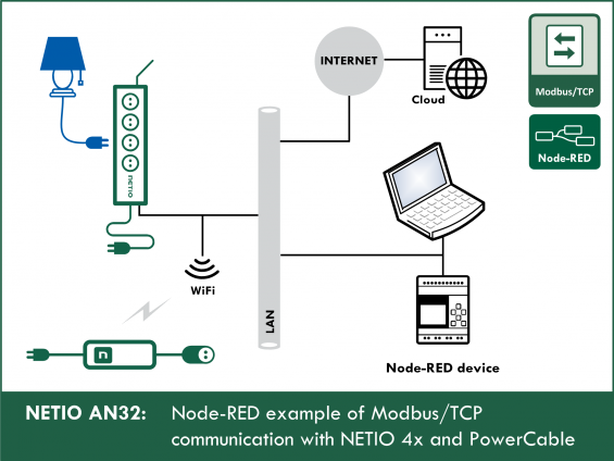
The AN32 Application Note shows two examples of working with NETIO smart outlets using the Modbus/TCP protocol.
-
AN32a is a demonstration/tutorial example to show the control of output 1.
- AN32b is a complete version that can be used in practice for your Node-RED projects; it takes into account possible issues with timing, multiple simultaneous requests, and so on.
The AN32a Node-RED flow example demonstrates the control of output no. 1 from the Dashboard that runs in the Node-RED environment.
Five buttons displayed in the Dashboard call the five possible actions that can be performed with the output (off, on, short off (restart), short on, toggle) using a Modbus Flex Write node (Write Single Register (0x06)).
The Dashboard periodically (every 1 s) updates the states of all outputs as well as the measured electrical values from the NETIO 4x device (frequency, voltage, total load), as long as the device is capable of measuring them. To read the output states and measured values, periodic reading of registers is used (Read Holding Registers (0x03)).

AN32b, the second Node-RED flow example, demonstrates complex control of all outputs from the Node-RED Dashboard.
There are five buttons for each output displayed in the Dashboard to call the five possible actions that can be performed with the given output (off, on, short off (restart), short on, toggle) using a Modbus Flex Write node (Write Single Register (0x06)).
The dashboard periodically updates (every 1 s) the states of all outputs as well as the measured electrical values from the NETIO 4x device (current, voltage, total load, frequency, short time, ...), as long as the device is capable of measuring them.
To read the output states and measured values, periodic reading of registers is used (Read Holding Registers (0x03)).
Details about the M2M protocol: Modbus / TCP - description of NETIO M2M API interface - PDF
Examples of using NETIO with Node-RED:
- AN32: Node-RED example of Modbus/TCP communication with NETIO 4x / PowerCable
- AN29: Node-RED example of URL API communication with NETIO 4x
- AN30: Node-RED example of REST JSON communication with NETIO 4x
- AN31: Node-RED example of XML communication with NETIO 4x
Flow (Node-RED script) for AN32a (tutorial version):

Dashboard for AN32a:

How does the Modbus/TCP protocol work
Actions applicable to each output (electrical socket)
In all M2M protocols, NETIO power socket devices use the same actions that can be applied to individual outputs. For example, a Toggle or Short Off action can be written to any output. For Short On and Short Off actions, the Modbus/TCP protocol uses its own “short” time that is defined over Modbus.
Actions with an output:
- 0 = Output switched off (Off)
- 1 = Output switched on (On)
- 2 = Output switched off for a short time (short Off)
- 3 = Output switched on for a short time (short On)
- 4 = Output switched from one state to the other (toggle)
- 5 = Output state unchanged (no change)
In the Modbus/TCP protocol, the devices are controlled using “functions”.
Using a Modbus/TCP function (01–16), an action (0–5) is sent to the NETIO 4x smart socket device.
Modbus/TCP functions
- 01 = Read Coils (NETIO: reads the on/off state of one output)
- 02 = Read Discrete Input
- 03 = Read Holding Registers (NETIO: reads e.g. the number of outputs)
- 04 = Read Input Registers (NETIO: reads the measured values)
- 05 = Write Single Coil (NETIO: sets the on/off state of an output)
- 06 = Write Single Register (NETIO: performs the chosen action, such as toggling the state, with an output)
- 15 (0x0F) = Write Multiple Coils
- 16 (0x10) = Write Multiple Registers
For a detailed description of how to control NETIO 4x using Modbus/TCP, see: NETIO -> Support -> Download -> Modbus / TCP - description of NETIO M2M API interface - PDF
A simple Modbus/TCP usage example is shown in AN27.
Configuring NETIO 4x
In the NETIO 4x (NETIO 4 / 4All / 4C) web administration, go to M2M API Protocols - Modbus/TCP, check Enable Modbus/TCP, and if necessary set the port number.
To allow the control of individual outputs, the Enable WRITE box must be checked. The IP address filter can be configured here, too.


NETIO 4All Online demo
The Online demo is a physical NETIO device connected to the Internet at a public IP address. The manufacturer makes available a demo device of each model. The online demos have different configurations, so it is possible to test the behavior without having the devices physically in hand.
In the online demos, configuration changes cannot be saved.
To access the online demo of a product, click “TRY ON-LINE DEMO” at the respective product page.
Node-RED
Node-RED is a programming tool for wiring together hardware devices, APIs and online services in new and interesting ways. Node-RED provides a browser-based flow editor and a wide choice of nodes and options. It is built on node.js, making it ideal to run on low-cost hardware such as the Raspberry Pi as well as in the cloud.
AN32a flow (script) – download
The Node-RED configuration is specified in a JSON structure and can be copied and pasted via the clipboard.
Importing the AN32a flow to node-RED
In the menu, select Import -> Clipboard.
Then, copy the text to the indicated field and click Import.

Installing missing nodes
The nodes are loaded into the selected flow. It is possible that an error message is displayed with a list of nodes that are being imported but are not installed in Node-RED yet. In this case, the missing nodes need to be installed.
If there are nodes missing, select Manage palette in the menu, click Install and find the missing nodes.
For more details, see AN29.
How does the AN32a (Modbus/TCP) Flow work

AN32a primarily consists of two parts: WRITE and GET.
WRITE: Writing to O1
- Five buttons are displayed in the Dashboard. They all control output 1 and invoke different actions.
- After clicking the ON button in the Dashboard, the payload is set to the action number (defined for each of the buttons in line with the actions that can be performed with the output).
- The Output 1 control node sets msg.payload to the correct format so that it can be used as an input parameter to Modbus Flex Write. For example: msg.payload = { value: msg.payload, 'fc':6,'unitid':1, 'address': 101 , 'quantity': 1 } return msg;
- The Msg.payload node displays the output from the Modbus Flex Write node.
GET: Reading from O1 – O4
- Every second, the timestamp node activates the Modbus Flex Getter nodes that read values from the NETIO 4x device.
- The Voltage request node sends a GET request to read the voltage value from the NETIO 4x device.
- The Frequency request node sends a GET request to read the frequency value from the NETIO 4x device.
- The OTPF request node sends a GET request to read the OTPF value from the NETIO 4x device.
- The Modbus Flex Getter node reads values from the NETIO 4x device according to the address and the function it receives as inputs.
- The /10, /100 and /1000 nodes divide the number received as a response from the Modbus Flex Getter node, so that it is displayed in the Dashboard with the proper order of magnitude.
- The Function node assigns the current states of NETIO 4x outputs as read by the Modbus Flex Getter into the msg object properties, so that the states can be displayed in the Dashboard.
- Various output nodes then follow in order to display selected properties of the msg object, as taken from the JSON object, in the Dashboard.
The msg object and msg.payload
For a simple and concise explanation, see here:
http://www.steves-internet-guide.com/node-red-message-object/

Description of nodes used
Button node
Adds a button to the Dashboard.
Clicking the button node generates a message containing the number of the action.
The number is the payload.
Possible actions with the outputs are:
- 0 = Output switched off (Off)
- 1 = Output switched on (On)
- 2 = Output switched off for a short time (short Off)
- 3 = Output switched on for a short time (short On)
- 4 = Output switched from one state to the other (toggle)
- 5 = Output state unchanged (no change)

Output 1 control
Receives the msg.payload from the Button node, containing the number of the action (1 = on, 4 = Toggle, and so on).
Formats msg.paylaod so that it is accepted as input by the Modbus Flex Write node.
value: msg.payload, = action
'fc': 6, = Modbus action for writing.
'unitid': 1, = unit ID (ignored)
'address': 101 , = address of the output (101 = 1, 102 = 2, 103 = 3, 104 = 4)
'quantity': 1 = number of outputs to work with. In this case, we work with output 1.

Modbus Flex Write
Switches (writes) the NETIO 4x device outputs.
Modbus/TCP write function
- 05 = Write Single Coil (NETIO: sets the on/off state of an output)
- 06 = Write Single Register (NETIO: performs the chosen action, such as toggling the state, with an output)
- 15 (0x0F) = Write Multiple Coils
- 16 (0x10) = Write Multiple Registers
The server is set to the NETIO 4All online demo.
The Host is the IP address of the online demo (may change in the longer term).
The Modbus/TCP protocol cannot use a DNS name; therefore, it is necessary to find out the IP address of the online demo.
For details about working online with the Modbus/TCP protocol, see AN27.
The port is set to the TCP port (502).
If you want to use your own device, the IP address should be changed here.
Instead of the NETIO 4All online demo, the PowerPDU 4C online demo can be used, too.


Debug node
Displays the msg.payload.
By default, it is set to msg.payload, and therefore it displays the server response in Node-RED.

Inject node
Every second, this node activates all Modbus Flex Read nodes. As a result, the values in the Dashboard are updated with a period of one second.

Voltage request
Sends a request to the Modbus Flex Read node to read the voltage.
Formats msg.payload so that it is accepted as input by Modbus Flex Read.
value: msg.payload, = not important
'fc': 4, = modbus function to read the measured values
'unitid': 1, = ignored
'address': 1, = address of the register holding the voltage value.
'quantity': 1 = number of registers to read.

Frequency request
Sends a request to the Modbus Flex Read node to read the frequency.
Formats msg.payload so that it is accepted as input by Modbus Flex Read.
value: msg.payload, = not important
'fc': 4, = modbus function to read the measured values
'unitid': 1, = ignored
'address': 0, = address of the register holding the frequency value.
'quantity': 1 = number of registers to read.

OTPF request
Sends a request to the Modbus Flex Read node to read the Overall True Power Factor.
Overall = calculated value for the entire device.
Formats msg.payload so that it is accepted as input by Modbus Flex Read.
value: msg.payload, = not important
'fc': 4, = modbus function to read the measured values
'unitid': 1, = ignored
'address': 2 , = address of the register holding the Overall True Power Factor value.
'quantity': 1 = number of registers to read.

/10, /100 and /1000
These simple function nodes divide the msg.payload value, as received from the Modbus Flex Getter node, so that it is displayed in the Dashboard with the correct order of magnitude.

Output states request
Sends a request to the Modbus Flex Read node to read all output states from the NETIO 4x smart sockets device.
Formats msg.payload so that it is accepted as input by Modbus Flex Read.
value: msg.payload, = not important
'fc': 3, = modbus function to read the measured values
'unitid': 1, = ignored
'address': 101 , = address of the register with the state of output 1.
'quantity': 4 = number of registers to read. Set to 4 since we are reading 4 states of the 4 outputs,
starting with the address 101 (output 1) and ending with the address 104 (output 4).

Function
Assigns values received from the Modbus Flex Read node
to properties of the msg object.


Also sets the text colors in the Text node in the dashboard to react to the value.

Text node
Displays a text field in the Dashboard.
In AN32, it is used to display the current, voltage, frequency and Overall True Power Factor.
The Label is displayed in the Dashboard, and the Name is the node name displayed in the flow in Node-RED.
{{msg.O1_Color}} changes the text color according to the {{msg.O1_State}} value.


Gauge node
This node adds a gauge widget to the Dashboard.

Node-RED Dashboard
The Dashboard is a graphical representation of dashboard elements.
The AN32a Dashboard can be opened by clicking the indicated symbol, or at the address of your Node-RED server with ui appended, e.g.: 127.0.0.1:1880/ui


The menu in the AN32a Dashboard includes a link to NETIO products website:

AN32b – complex version
AN32b provides for complete control of outputs 1 – 4. Each output has its own 5 control elements (ON, OFF, SHORT ON, SHORT OFF, TOGGLE) on the Dashboard. Current status is periodically read and displayed.
Modbus Flex Write and Modbus Flex Read nodes pose a problem: when the number of requests is high, new requests are queued and processed in sequence. When a certain number of requests is reached, new requests are not even queued anymore.
In AN32b, this problem is solved with Delay nodes and a control variable that split one period into several parts. This prevents generating a large number of requests at once and avoids this bottleneck.
AN32b import script
The Node-RED configuration is specified in a JSON structure and can be pasted via the clipboard.
Flow (Node-RED script) for AN32b (complex version):

Dashboard for AN32b:

FAQ
1) Is it possible to use an IP address different from the pre-filled one?
Yes, the IP address can be specified in the Modbus Flex nodes by changing the Host value in the Server properties.
2) Is it possible to control a different output than the output No. 1?
Yes. Assuming the device has several outputs, the number of the output can be changed by changing the address in the Output 1 control node.
Example: msg.payload = { value: msg.payload,
'fc': 6,
'unitid': 1,
'address': 102 ,
'quantity': 1 }
return msg;
3) I have changed the flow in Node-RED but the changes are not reflected in the Dashboard.
To save and display all changes in the flow, it is necessary to click Deploy in the upper right-hand corner in Node-RED.
4) How can I install Node-RED on my PC?
The official Node-RED website provides detailed instructions and a free installer.
Website: https://nodered.org/docs/getting-started/
5) Is it possible to install Node-RED on devices other than a PC?
Yes, Node-RED can run e.g. on Raspberry Pi, Arduino or Microsoft Azure.
6) Is it possible to specify a DNS name instead of a numerical IP address?
No. Unfortunately, due to restrictions of Modbus nodes in Node-RED, this is not possible. The IP address of your NETIO 4x device can be found out e.g.with the NETIO discover utility in the local network.
To find out the IP address of an online demo, use the ping command, as described in AN27.
7) In the debug section of Node-RED, “Address Not Valid” is shown.
The address value is invalid.
8) In the debug section of Node-RED, “FC Not Valid” is shown.
The function value is invalid.
9) In the debug section of Node-RED, “Quantity Not Valid” is shown.
The quantity value is invalid.
Supported FW versions for NETIO 4x:
3.1.0 and higher (Firmaware archive)
Supported FW versions of PowerCable xxx:
2.0.2 and higher (Firmware archive)